
Quick answer: Spare Parts Maintenance on a shot blasting machine is not a list of parts to buy — it is a fixed-interval wear programme built around five measured numbers. Replace Blades as a balanced set of eight when the tip has lost 10 mm of its original 25 mm section or when the set reaches 50% wear; replace the Impeller and distributor at 3 mm of wear; condemn chamber liners at 30% of remaining thickness; torque blade clamp Bolts to 85–95 N·m and the wheel nut to 320–380 N·m; log every action against running hours, not calendar dates. A plant that follows a shift-to-annual calendar of this type typically runs 1,800–2,200 hours between unplanned wheel stoppages, against 600–900 hours for a run-to-failure regime. The parts cost the same either way. What changes is how many of them you buy per year and how many tonnes of steel you fail to clean.
In most audits of premature blast wheel failure, the casting is not the problem. The failure sequence starts somewhere else: a blade replaced on its own instead of as a set, which throws the rotor out of balance; a wheel nut reused three times until the thread yields; a control cage bolted down with an impact gun and no torque wrench, so the cage sits 0.4 mm off centre and the blast pattern drifts into one corner of the chamber; a distributor run 200 hours past its wear limit so abrasive leaks between cage and impeller and grit-blasts the housing faces.
The cost of that pattern is easy to quantify. A 360 mm class wheel running two shifts consumes roughly one set of eight blades per 700–900 hours. If blades are changed one at a time, average set life falls to 450–550 hours, because a new blade in a worn set works harder and the resulting imbalance loads the shaft bearings. That is 30–40% more blade sets per year, plus a bearing change every 4,000–5,000 hours instead of 9,000–12,000, plus the downtime for both jobs. Good spare parts maintenance is therefore mostly about discipline in three areas: measuring wear instead of guessing it, replacing in matched sets, and recording what was done so the next interval can be planned from data.
This guide sets out a practical maintenance calendar for the wear parts around a blast wheel — blades, impeller, distributor, control cage, liners, Feed Duct, guards and fasteners — with the measurement methods, condemn limits, torque values and interval tables needed to run it without a factory-trained technician on site. It is written for maintenance planners, foundry engineers and buyers who order the parts and then have to defend the annual spend.
A wheel assembly has six areas that consume spares, and each one fails in a different way. Understanding the failure mode is what tells you whether the fix is a part, a setting or an operating change.
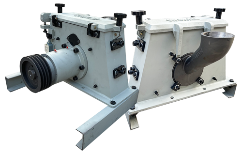
The photograph above shows two complete wheel assemblies side by side. The unit on the left carries the belt pulley and drive guard; the unit on the right shows the curved feed duct entering the housing cover. Both are the same family of casting, which matters for maintenance planning: the housing, cover and mounting base rarely need replacement, so the annual parts budget should be concentrated almost entirely in the six zones listed above rather than in the structure around them.
Every replacement decision on a blast wheel should trace back to a measurement. A maintenance planner who records these five numbers at each shutdown can forecast the next two part orders with reasonable accuracy, and can argue a warranty claim with evidence instead of opinion.
| Measured item | Instrument | New / reference value | Condemn limit | Check interval |
|---|---|---|---|---|
| Blade tip thickness | Vernier or ultrasonic gauge | 25 mm at tip, 12 mm at root | 15 mm at tip, or 50% of set life used | Weekly |
| Impeller outlet step | Straight edge + feeler | 0–0.5 mm | 3 mm | Weekly |
| Control cage window width | Vernier across slot | Nominal +0 mm | Nominal + 6 mm | Weekly |
| Liner remaining thickness | Ultrasonic or depth gauge | 40 mm (chamber), 25 mm (wheel side) | 30% of original | Monthly |
| Rotor vibration (RMS) | Hand-held vibrometer at bearing housing | < 2.8 mm/s | 4.5 mm/s alarm, 7.1 mm/s stop | Weekly |
Record the numbers against running hours, not dates. A machine that runs 4,000 hours a year and one that runs 1,200 hours a year cannot share a calendar. If the plant has no hour meter on the wheel motor, fit one; it is the cheapest instrument in the whole maintenance kit and it converts every other interval from guesswork into arithmetic.
The table below is the core of the programme. It assumes two-shift operation on steel shot or angular grit, with the wheel running 12–16 hours a day. Scale the intervals by running hours, not by weeks, for single-shift plants.
| Frequency | Task | Accept / reject criterion | Time |
|---|---|---|---|
| Every shift | Listen at the wheel cover; check motor current against baseline; confirm abrasive hopper level; check blast pattern on a test plate if finish quality is in question | No rattle or knocking; current within ±5% of baseline; pattern centred within ±50 mm | 5–10 min |
| Daily | Inspect blades through the inspection door; check blade clamp bolts for looseness; clean the separator screen; drain the air receiver and filter water trap; check door seals for abrasive leakage | No bolt movement by hand; no abrasive on the floor at door seals | 20–30 min |
| Weekly | Measure blade tip thickness; measure impeller step; measure cage window; check V-belt tension (10 mm deflection at mid-span); grease wheel bearings; check blast pattern and adjust the cage position if the hot spot has moved | All five numbers inside the limits above | 45–60 min |
| Monthly | Remove and inspect the complete rotor stack; check axial float; inspect liners and side plates; check feed duct and directional sleeve bore; check guard fit and cap nuts; verify motor-to-wheel alignment | Axial float ≤ 0.15 mm; liners above 30%; no hole in duct | 2–3 h |
| Quarterly | Dynamic balance check of the rotor; replace the blade set as a matched eight; inspect the control cage seat and housing faces for abrasive erosion; check the abrasive valve and separator curtain; oil change on the reducer | Balance grade G6.3 or better; no step at cage seat | 4–6 h |
| Annual | Full teardown: bearings, shaft, housing faces, chamber liners, door seals, dust collector filter cartridges; dimensional check of the housing mounting face; review the parts consumption log against the previous year | Bearing clearance within manufacturer limit; housing face flat within 0.1 mm | 1–2 days |
Two rules keep this calendar honest. First, no task is signed off without a number written next to it; "blades checked" is not a record, "blade tip 18.2 mm, next check at +150 h" is. Second, the weekly and monthly tasks must be done with the wheel stopped and locked out. A blast wheel coasting down from 2,900 rpm takes 40–90 seconds, and the interlock is the only thing standing between a hand and eight blades moving at 90 m/s rim speed. Lock out, tag, verify zero energy, then measure.
Most maintenance-induced failures come from a setting rather than a worn part. These are the values that matter, and they should be printed on a laminated card and kept in the tool kit that goes to the machine.
| Fastener / setting | Thread | Torque | Notes |
|---|---|---|---|
| Blade clamp bolt | M12 × 1.75, class 8.8 | 85–95 N·m | Replace at every blade change; never reuse a stretched bolt |
| Cap nut on blade stud | M12 | 80–90 N·m | Apply anti-seize; re-torque after first 4 h of running |
| Wheel retaining nut | M20 × 2.5 | 320–380 N·m | Left-hand thread on most assemblies; mark and witness |
| Housing cover bolts | M16, class 8.8 | 190–210 N·m | Cross-pattern, two passes |
| Control cage clamp | M10 | 45–55 N·m | Set cage position first, then torque |
| Blade tip to cage clearance | — | 0.8–1.2 mm | Feeler gauge at three points, 120° apart |
| Impeller to distributor gap | — | 0.5–1.0 mm | Below 0.3 mm the parts rub; above 1.5 mm abrasive spills |
| Rotor axial float | — | 0.05–0.15 mm | Dial indicator on the shaft end |
| Balance quality | — | G6.3 at 2,900 rpm | Residual unbalance ≤ 8 g·mm per kg of rotor mass |
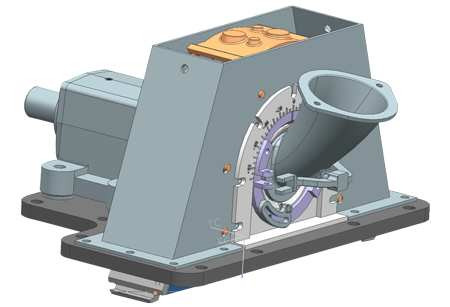
The cutaway rendering makes the clearance stack visible: abrasive falls through the feed duct, is picked up by the impeller, passes through the distributor window and enters the blade root, then leaves at the tip. Each transition is a wear interface and each one has a gap that must stay inside its tolerance. When a machine "loses power" without a motor fault, the cause is almost always one of these three gaps opening up — most often the cage window at +6 mm, sometimes the impeller step at 3 mm, occasionally both at once after a long run without measurement.
Balancing deserves a separate note. A wheel is balanced as an assembly, not as individual parts. Fitting one new blade to a set of seven worn blades moves the centre of mass by several grams, and at 2,900 rpm that produces a force that grows with the square of speed and quietly destroys the drive-end bearing. Replace blades in matched sets of eight, from the same casting batch where possible, and check balance at the quarterly service. If a set must be rotated early because of a single broken blade, replace all eight, not the broken one.
Spare parts maintenance intervals are not transferable between wheel sizes. A plan written for a 360 mm universal wheel will over-maintain a small four-impeller unit and under-maintain a 500 mm heavy-duty assembly. The table below gives the reference figures used for planning; confirm the final numbers against the machine nameplate and the part drawing.
| Wheel class | Nominal diameter | Blades per set | Drive power | Abrasive flow | Typical blade life | Service interval (blades) |
|---|---|---|---|---|---|---|
| Small four-impeller class | 250–300 mm | 4 | 5.5–7.5 kW | 40–80 kg/min | 600–900 h | Every 300 h measure |
| 360 mm universal class | 360 mm | 8 | 11–15 kW | 90–140 kg/min | 500–850 h | Every 250 h measure |
| 380 series class | 380 mm | 8 | 15–18.5 kW | 110–160 kg/min | 480–800 h | Every 250 h measure |
| 500 mm heavy-duty class | 500 mm | 8 | 22–30 kW | 200–280 kg/min | 400–700 h | Every 200 h measure |
| 034 square-corner class | 340–360 mm | 8 | 11–18.5 kW | 90–150 kg/min | 450–750 h | Every 250 h measure |
| U105 series class | 360–420 mm | 8 | 15–22 kW | 120–200 kg/min | 420–700 h | Every 200 h measure |
| Big four-impeller class | 420–500 mm | 4 (large section) | 18.5–30 kW | 150–260 kg/min | 500–800 h | Every 250 h measure |
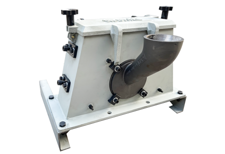
Note the inverse relationship between wheel size and blade life. A 500 mm wheel throws more abrasive per minute, at higher tip speed, and consumes its blades faster in hours even though it cleans more steel per hour. When someone compares blade life between two plants, the first question to ask is which wheel class they are running. Comparing a 300 mm unit at 700 hours with a 500 mm unit at 700 hours is not a comparison of casting quality; it is a comparison of duty.
Spare parts maintenance planning needs a material baseline, because wear rate is a function of hardness, carbide volume and section thickness, not of price. The table below lists the benchmarks that a maintenance buyer should see on a part drawing or inspection certificate.
| Part | Typical alloy | Hardness | Weight range | Wear mechanism | Repairable? |
|---|---|---|---|---|---|
| Blade | High-chrome white iron, 26–28% Cr | HRC 62–66 | 1.0–1.6 kg (360 class); 2.4–3.4 kg (500 class) | Low-stress abrasion, tip erosion | No |
| Impeller | High-chrome white iron, 22–26% Cr | HRC 60–64 | 2.2–4.5 kg | Chipping and pocket wear | No |
| Distributor / control cage | High-chrome iron with machined slot | HRC 58–63 | 1.8–3.6 kg | Slot widening, edge rounding | No |
| Wheel Side Liner | High-chrome or alloy steel plate | HRC 52–60 | 6–14 kg | Sliding abrasion | No |
| Chamber liner | Manganese steel or high-chrome plate | HB 200–250 (Mn); HRC 55+ (Cr) | 18–45 kg | Impact plus abrasion | Weld build-up possible |
| Feed duct / directional sleeve | High-chrome iron, cast bend | HRC 55–62 | 3–8 kg | Erosion at bend and outlet | No |
| Blade bolt and cap nut | Class 8.8 / 10.9 steel, coated | — | 0.06–0.15 kg | Fatigue, thread yield | No — replace |
Two practical consequences follow from this table. First, weight is a specification, not a detail: a blade that is 8% lighter than the drawing has less wear allowance and will reach its condemn limit sooner, so weigh a sample from each delivery. Second, hardness alone does not predict life. A blade at HRC 64 with a brittle matrix will chip at the tip when a tramp bolt enters the wheel, while a blade at HRC 61 with a tougher matrix will survive and keep its pattern. That is why incoming inspection should include a hardness reading at three points plus a visual check for cold shuts and misruns along the leading edge.
The same wheel in two different plants can differ by a factor of two in parts consumption. The variables are abrasive type, abrasive reclamation quality, workpiece shape and how hard the operators push the machine.
| Industry | Typical duty | Dominant wear driver | Blade life | Maintenance emphasis |
|---|---|---|---|---|
| Iron and steel foundry | 2–3 shifts, desanding castings | Sand carry-over into the abrasive, high dust load | 380–550 h | Separator adjustment, daily screen clean, dust collector |
| Steel structure fabrication | 2 shifts, plate and sections | Continuous duty, high abrasive flow, long blast patterns | 500–750 h | Pattern check, cage window measurement, liner thickness |
| Shipyard and offshore | 1–2 shifts, plate preparation | Salt contamination, coarse grit, heavy reclamation load | 420–650 h | Feed duct erosion, door seals, corrosion of fasteners |
| Forging and heat treatment | 2 shifts, scale removal | Hot, scaly workpieces, abrasive contamination | 450–650 h | Bearing temperature, seal integrity, duct wear |
| Automotive casting | 3 shifts, high volume | Running hours, tight finish tolerances | 350–500 h | Vibration trend, balance, planned weekend windows |
| Rail and heavy equipment | 1–2 shifts, large castings | Impact loading, large workpieces, wide pattern | 400–600 h | Housing faces, guard condition, blade breakage checks |
Foundries are the hardest case, and not because of the castings. Sand that escapes the knockout station enters the abrasive circuit, and the separator cannot remove all of it. Sand is softer than steel shot but it absorbs impact energy at the blade tip and changes the flow pattern inside the wheel, so blades wear unevenly. Maintenance in a foundry should spend as much time on the separator and the dust collector as on the wheel itself: a separator delivering a dirty curtain will shorten blade life by 20–30% regardless of the casting quality.
Buyers tend to think in tonnes of steel cleaned; maintenance planners think in hours. Both are useful, and the conversion is worth keeping on one line of the maintenance log because it lets you compare two machines of different sizes on a like-for-like basis.
| Part | Reference life (hours) | Tonnes per replacement (typical) | Early-warning symptom | Failure if ignored |
|---|---|---|---|---|
| Blade set (8) | 500–850 | 2,500–6,000 t | Pattern widens, finish slows, current drifts up 3–5% | Tip breakthrough, blade break-up, liner damage |
| Impeller | 900–1,400 | 5,000–9,000 t | Abrasive appears in the housing cavity | Housing face erosion, cage seat damage |
| Distributor / cage | 600–1,200 | 3,500–8,000 t | Hot spot moves, coverage uneven | Lost throughput, uneven surface profile |
| Wheel side liner | 1,200–2,000 | 7,000–14,000 t | Rubbing marks on blade sides | Housing penetration, abrasive leak |
| Chamber liner | 1,800–3,000 | 10,000–20,000 t | Visible dishing, paint wear pattern | Structural damage, unplanned rebuild |
| Feed duct | 1,500–2,500 | 9,000–16,000 t | Reduced flow at fixed valve setting | Hole through wall, abrasive loss |
| Blade bolts | One blade change | — | Thread stretch, rounded hex | Blade release at speed — serious hazard |
The tonne figures assume a 360 mm class wheel at 120 kg/min and 8 hours of effective blasting per shift. Recalculate for other classes: a 500 mm wheel at 240 kg/min doubles the tonnage per hour but shortens the hour life, so the tonnes-per-set figure lands in a similar range. If your machine's tonnes-per-set is far below the table, the problem is usually abrasive quality or separator setting, not the parts.
Between planned services, four cheap checks catch nearly every developing failure. None of them requires instrumentation beyond a vibrometer, a clamp meter and a test plate.
These four numbers, kept on one sheet per machine, turn maintenance from a reactive repair function into a planning function. They also settle the recurring argument about whether a part failed early because of the casting or because of the way the machine is run.
A planned blade set change on a 360 mm wheel with good access takes 90–120 minutes for two technicians. The same job on a wheel that has seized, with a broken blade jammed against a liner, takes 12–16 hours and usually consumes a liner and a set of bolts as well. The work sequence for the planned version is worth standardising.
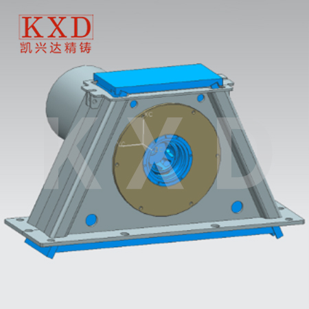
Having an assembly drawing on the wall next to the machine is not decoration. It shortens the learning curve for new technicians, it makes the parts list unambiguous when ordering, and it prevents the classic error of fitting a cover gasket on the wrong face. The colour-coded assembly above separates the housing, cover, rotor stack and duct, which is exactly the order in which the parts come off and go back on.
The workshop photograph shows a rotor sitting in its housing with the cover removed — the same view a maintenance technician sees at step 6 of the sequence. Use this view for training: point out the blade roots, the impeller, the cage seat and the side liner, and have the technician measure each one before touching a spanner. A technician who can name the six wear zones and state the condemn limit for each will do a better job than one who has memorised a torque table.
The maintenance file is the asset that makes next year's budget defensible. It does not need software; a spreadsheet with one row per service event is enough, provided the columns are consistent.
Four KPIs come out of that table directly. Mean time between failures (MTBF) should be targeted at 1,800–2,200 running hours for wheel-related stoppages. Mean time to repair (MTTR) should stay under 3 hours for planned work and under 8 hours for unplanned. Planned maintenance compliance — tasks completed on schedule — should exceed 95%; below 85%, the failure statistics will start to drift upward within one quarter. Cost per tonne of steel cleaned typically sits between 0.30 and 0.90 currency units for wear parts on a well-run machine, and rises above 1.20 when blade sets are changed individually rather than in matched eights.
Two documents complete the file: the part drawing with material and hardness specification, and the incoming inspection record for each delivery. Together they settle most warranty discussions before they start, because they show what was ordered, what arrived and what it measured.
Use this list when specifying or reordering the wear parts that the maintenance calendar consumes. Each line corresponds to a real failure mode described above.

A quality management certificate is a starting point, not a guarantee. What it does tell a maintenance buyer is that the supplier has a documented inspection process and a traceability system, which are the two things needed when a blade fails at 600 hours and you want to know whether the batch was wrong. Ask for the certificate scope, the validity dates and the certification body — and ask for the inspection record for the actual batch you are buying, because a system certificate says nothing about a specific casting.
Measure blade tip thickness every 200–250 running hours and replace the set when the tip reaches 15 mm from a new 25 mm, or when the set has used 50% of its expected life. In practice that is 500–850 hours on a 360 mm class wheel running steel shot, and 400–700 hours on a 500 mm heavy-duty wheel. Always replace all eight blades together.
No. A mixed set has an unbalanced mass distribution, and at 2,900 rpm the resulting vibration loads the shaft bearings and the cage seat. The cost saved on three blades is smaller than the cost of one bearing change, and the imbalance also distorts the blast pattern, which shows up as uneven surface finish.
Replace the cage when the window width has grown 6 mm over nominal, or when the slot edge is rounded enough to spread the blast pattern by 20 mm at the test plate. Measure across the slot with a vernier at the same point each time. A worn cage is the most common cause of a machine that "has lost power" while drawing normal current.
Look for abrasive in the housing cavity and for a step at the impeller outlet. Use a straight edge and feeler gauge: anything above 3 mm means replacement. A second symptom is a blade set that wears at the root before the tip — that indicates abrasive is entering the blade at the wrong angle because the impeller is worn.
Between 0.05 and 0.15 mm, measured with a dial indicator on the shaft end. Less than 0.05 mm means the bearings are preloaded or the spacer stack is wrong; more than 0.15 mm means the rotor can move axially under load, which accelerates cage and impeller wear and can produce a knocking sound at start-up.
85–95 N·m for an M12 class 8.8 blade clamp bolt, and 80–90 N·m for a cap nut on an M12 stud, with anti-seize applied. Use new bolts at every blade change and re-torque after the first four hours of running, because the casting settles and preload drops.
Higher ambient temperature raises the dust collector inlet temperature and reduces air density, so extraction volume falls and the abrasive curtain in the separator becomes dirtier. The wheel then runs on contaminated abrasive. Check filter pressure drop and extraction volume in hot weather, and clean or replace cartridges before the season rather than during it.
Keep them dry, on a pallet, off the floor, in the original packing, and not stacked more than two high. High-chrome castings are hard but not tough: dropping a blade on a concrete floor can start a crack that only shows up at 400 hours. Store blades as matched sets with the batch label facing out, and keep fasteners in sealed bags with the grade marked.
Yes for plants running three shifts or with a single machine on a critical line. A complete assembly — housing, rotor, cage, duct — allows a swap in 3–4 hours instead of a 12-hour repair, and the removed unit can be rebuilt at a planned pace. For two-machine plants on day shift only, a rotor stack plus a blade set and cage is usually enough.
Add the cost of all wear parts consumed in a period, divide by the tonnes of steel cleaned in the same period. Include blades, impeller, cage, liners, duct and fasteners, and exclude labour if you want a pure parts figure. A well-run 360 mm machine normally lands between 0.30 and 0.90 per tonne; a figure above 1.20 usually indicates single-blade replacement or a separator problem.
Spare parts maintenance on a shot blasting machine is a measurement discipline first and a purchasing activity second. Measure blade tip thickness, impeller step, cage window, liner thickness and rotor vibration on a fixed hour-based interval; replace in matched sets; hold the torque and clearance values; and write the numbers down. The parts themselves are commodity castings — what separates a machine that runs 2,000 hours between wheel stoppages from one that stops every 700 hours is whether anyone measured the gap before it opened.
Start with the five numbers in this guide, apply the calendar to one machine for a quarter, and compare blade sets consumed against the previous quarter. In most plants the difference pays for the vibrometer in the first month, and the maintenance file becomes the document that justifies next year's spares budget without an argument.


CERTIFIED UNI EN
ISO 9001:2015
16-Q-0200122-TIC


In the past 20 years, we adhere to the concept of people oriented and commitment to integrity, strictly abide by the rules of safety in production, environment protection and occupational disease prevention, delicate to

 Español
 Pусский
 Deutsch
 Italiano


Comment
(0)